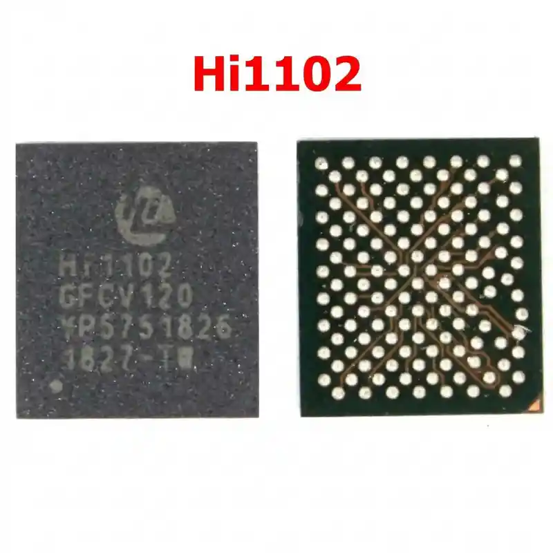
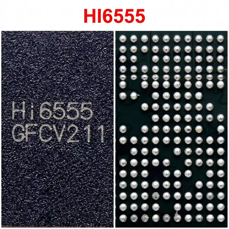
Hi6522-V223 IC
As low as
Rs 0.00
Worldwide shipping · Cash on Delivery
Product Details
1. ARCHITECTURAL OVERVIEW & CIRCUIT SPECIFICATIONS
The HiSilicon Hi6522-V223 is the dedicated Sub-PMIC and battery charging manager for Kirin 659/710 mobile architectures:
- Power-Path & Charging Stage: Regulates 5V / 9V VBUS input from Micro-USB or USB Type-C ports. Controls pre-charge, constant-current (CC), and constant-voltage (CV) charging loops through an external power inductor (typically 1.0 µH to 2.2 µH).
- System Rail Generation (VSYS): Uses NVDC power-path architecture to maintain system voltage above 3.5V, enabling immediate startup even with a flat or zero-volt battery.
- Auxiliary Rail Distribution: Integrates multi-channel buck converters and LDOs supplying intermediate rails to secondary peripherals (camera autofocus/image sensors, RF transceivers, audio amplifiers).
- System Communication: Communicates directly with the Kirin Application Processor via bidirectional I2C / SPMI lines, feeding back battery voltage, temperature (NTC), and charge current parameters.
2. HARDWARE DIAGNOSTICS & SYSTEM FAULT ISOLATION
Step 1: Bench Power Supply Current Draw Analysis (at 4.0V V_BATT):
- Primary VDD_MAIN Dead Short: If an immediate full-current short (2A - 5A) occurs before pressing the power key, the Hi6522-V223 high-side switching FET or an adjacent input decoupling capacitor has suffered punch-through breakdown.
- Low-Current Boot Freeze (40 mA - 70 mA): If pressing the power button causes current to rise to 40 mA - 70 mA and freeze, an auxiliary LDO or secondary buck rail driven by Hi6522-V223 is missing or shorted, halting the Kirin bootloader sequence.
Step 2: Passive Diode Mode Testing (Red probe on Ground, Black probe on test point):
- Locate the bank of SMD capacitors and the switching inductor surrounding Hi6522-V223:
* VBUS Input Capacitors: Expected normal diode drop ~0.500V - 0.620V. (0.000V indicates blown input protection TVS or shorted input FET).
* VBAT / VSYS Capacitors: Expected normal diode drop ~0.380V - 0.460V.
* Buck Inductor Phase Nodes: Expected normal diode drops range from ~0.280V to ~0.450V. (0.000V indicates a shorted output filter capacitor or punctured low-side MOSFET).
* I2C / SPMI Clock and Data Lines: Expected normal diode drop ~0.450V - 0.550V. (OL indicates broken board trace; 0.000V halts system boot).
Step 3: Thermal Localization:
- If a low-resistance short is detected on VSYS or a buck output, inject 1.2V (limited to 1.5A) directly onto the shorted line while monitoring with a thermal imaging camera or freeze spray. If the Hi6522-V223 body lights up instantly, internal silicon degradation is confirmed.
3. REQUIRED TOOLS & REWORK MATERIALS
- Precision Hot Air Rework Station (Quick 861DW, Atten ST-862D, Sugon 8620DX) with 5.0 mm angled nozzle.
- Micro-soldering iron station (JBC C210 / C245 or T12) equipped with a fine knife (K) or chisel tip.
- Stereo inspection microscope (20x - 45x magnification).
- Specialized ultra-thin curved underfill cleaning blade / micro-hook.
- Dedicated HiSilicon Hi6522 / Hi6522GWCV223 BGA reballing stencil (0.4 mm pitch, 0.12 mm thickness).
- Solder alloy: Sn63/Pb37 leaded solder wire (0.2 mm - 0.3 mm) and Sn63/Pb37 solder paste (183°C melting point).
- Consumables: Rosin-based tacky no-clean flux (Amtech NC-559-V2-TF), high-density copper desoldering braid (1.0 mm to 1.5 mm width), 99.9% pure Isopropyl Alcohol (IPA), high-temperature polyimide (Kapton) tape, aluminum foil heat shield.
4. STEP-BY-STEP UNDERFILL REMOVAL & REWORK PROTOCOL
Step 1: Board Securing and Thermal Shielding
- Fix the Huawei motherboard securely into an adjustable PCB repair clamp.
- CRITICAL SHIELDING: Huawei motherboards feature Kirin CPUs and eMMC/UFS flash memory in close proximity to the Hi6522-V223 Sub-PMIC. Both are heavily underfilled with heat-sensitive black resin.
- Cover adjacent CPU, memory, and camera FPC connectors with two layers of Kapton tape, topped with an aluminum foil deflector or copper heat-sink coin.
Step 2: Perimeter Underfill Epoxy Removal
- Set the hot air station to 200°C - 220°C with 30 LPM airflow.
- Heat the perimeter edge of Hi6522-V223 for 10-15 seconds to soften the tough factory black epoxy.
- Using an ultra-fine curved underfill scraping knife held at a 45° angle, carefully peel away the perimeter underfill fillet around all four borders of the IC.
- Exercise extreme caution: do NOT dig into the substrate to avoid severing multi-layer PCB traces or knocking off adjacent 0201 bypass capacitors.
Step 3: Desoldering and IC Extraction
- Apply a generous bead of tacky flux around the chip perimeter.
- Set hot air station to 335°C - 345°C with 40-45 LPM airflow.
- Hold the nozzle vertically (90°) at a distance of 1.5 cm, maintaining smooth circular motions around the chip for 25 to 35 seconds.
- Test solder liquidity by gently nudging an adjacent non-underfilled capacitor.
- When the solder reaches liquidus phase, lift the IC vertically using fine curved tweezers. Never pry, wedge, or twist the IC before the underfill has softened and solder is fully molten to prevent tearing motherboard BGA pads.
Step 4: Footprint Dressing & Underfill Cleanup
- Keep the board slightly warm (~180°C - 200°C) and scrape away remaining underfill glue from between the pads using a flat-edge micro-blade.
- Add fresh rosin flux. Tin the soldering iron tip (set to 340°C) with leaded Sn63/Pb37 solder and sweep across the footprint to dissolve and replace residual factory lead-free alloy (SAC305).
- Lay fine copper desoldering braid flat across the footprint. Lightly glide the iron over the braid without downward force to planarize all pads.
- Clean thoroughly with 99.9% IPA and an ESD foam swab. Inspect under the microscope for missing or torn pads.
- If any active signal pad has torn due to drop stress, scrape the trace, run a 0.02 mm insulated copper jumper wire, form a micro-pad loop, apply UV green solder mask, and cure with a 365 nm UV lamp for 60 seconds.
Step 5: Reballing the Replacement Hi6522-V223
- Ensure the underside of the replacement Hi6522-V223 is clean and completely planar.
- Align the chip into the matching Hi6522 BGA stencil under the microscope.
- Spread Sn63/Pb37 solder paste evenly across all apertures. Scrape flush with a clean razor blade and dry excess moisture with a lint-free cloth.
- Direct hot air at 280°C - 300°C with low airflow (15-20 LPM) from 3 cm distance, gradually moving closer until all apertures melt into uniform, bright 0.20 mm - 0.25 mm solder spheres.
- Allow the stencil to cool for 15 seconds, apply a drop of flux, reflow briefly for 2 seconds to round the balls, and release the IC.
Step 6: Alignment and Reflow Soldering
- Apply an ultra-thin, translucent film of tacky flux across the logic board footprint. Excess flux will cause this lightweight BGA chip to float and misalign during reflow.
- Position the Hi6522-V223 onto the footprint, aligning the Pin 1 corner index dot with the logic board silkscreen orientation mark.
- Apply vertical hot air at 320°C - 330°C with 35 LPM airflow.
- As the solder reaches 183°C, the IC will sink downward and self-align onto the pads via liquid surface tension.
- Execute the "tweezer tap" test: gently tap the corner of the chip body with tweezers; it must instantly bounce back into center alignment.
- Remove heat vertically and keep the board stationary.
Step 7: Post-Rework Verification & Testing
- Allow natural ambient cooling for 3-5 minutes. Never use freeze spray or compressed air to avoid thermal shock cracking inside the silicon die.
- Clean all flux residue with 99.9% IPA.
- Measure diode mode values across all peripheral buck inductors and VBUS/VBAT lines to verify zero solder bridging occurred under the array.
- Connect the motherboard to a DC bench power supply; confirm normal idle current consumption (0.000A before pressing power).
- Power on the device: verify smooth boot sequence into the EMUI operating system.
- Connect a USB charging cable through an inline power meter and confirm steady, full-rate charging current negotiation.
You may also like